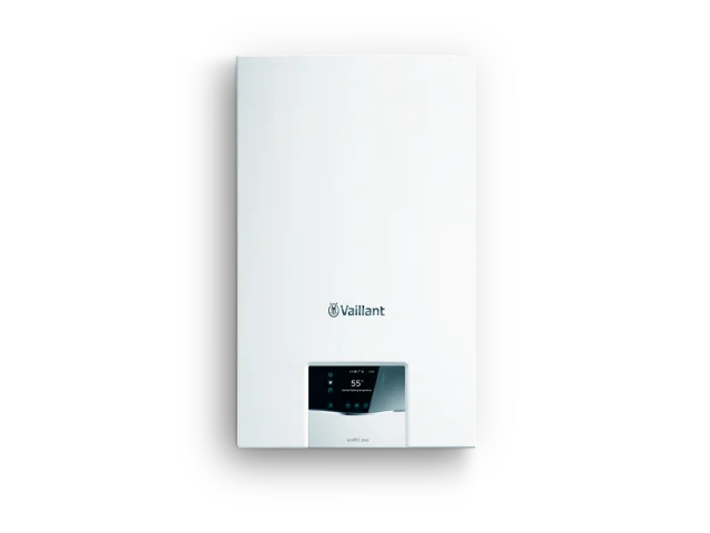
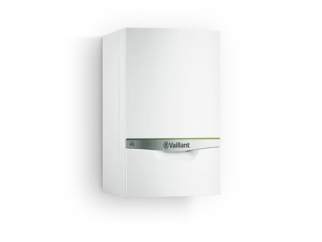
Book a new boiler installation from just £1900! Discover affordable heating solutions.
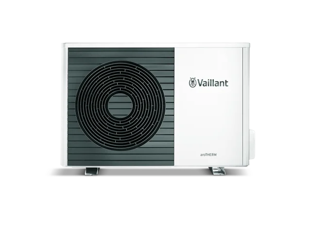
Discover the future of heating with our air source heat pump installations, Schedule a free site survey!
Ensure safety and efficiency with our professional boiler servicing for just £108. Schedule Today!
Need a boiler repair? Our hassle-free repair services start at an unbeatable £108 with "No Hourly Charge"
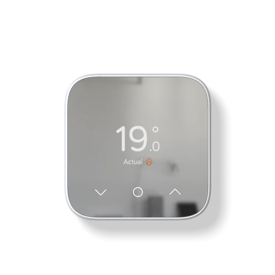
Buy a Smart Thermostat with installation starting at £220. Explore our selection today!
Upgrade to Combi Brilliance! Experience instant hot water and efficient heating from £2900!
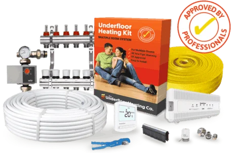
Experience ultimate comfort with our underfloor heating installations. Free site survey and design.
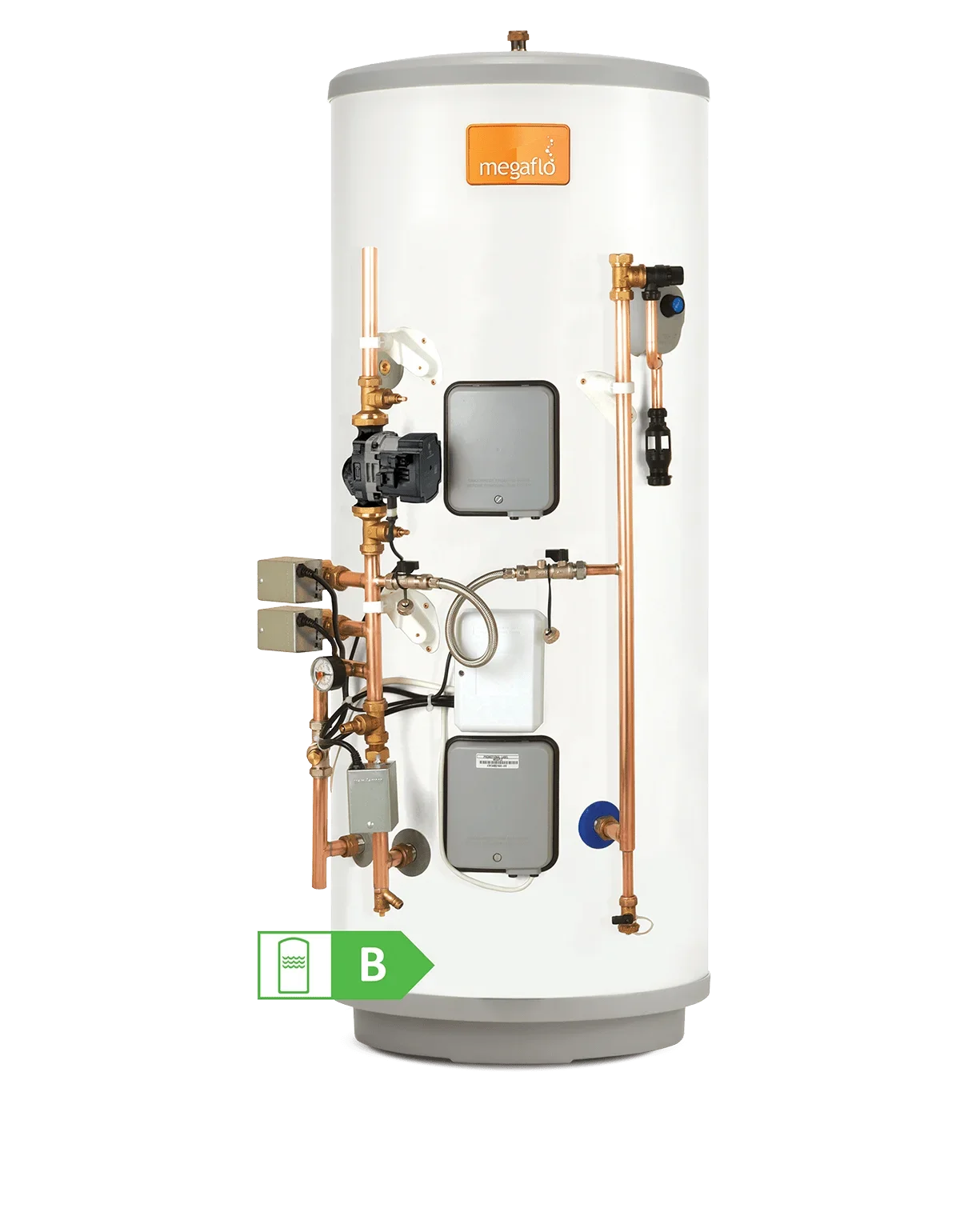
Buy an unvented cylinder with installation from £1395. Experience constant, high-pressure hot water.
Smart or Wireless
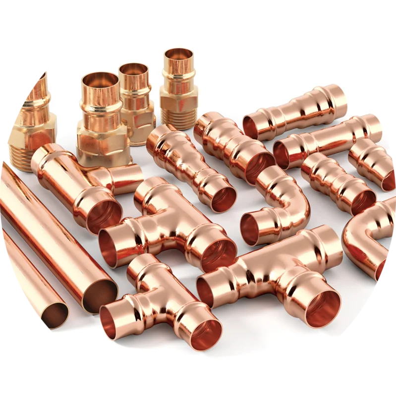
All New Boiler Prices include all Materials required
Check here
We take care of all paperwork

Once your price is fixed, it remains fixed.
Click here for Finance

Our new boiler installation deals include everything you need. Click here to get an Instant Boiler Quote for Free.
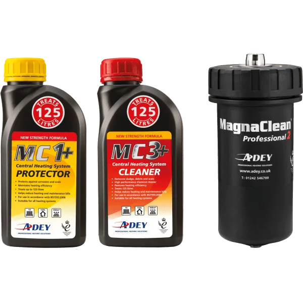
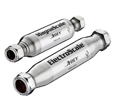
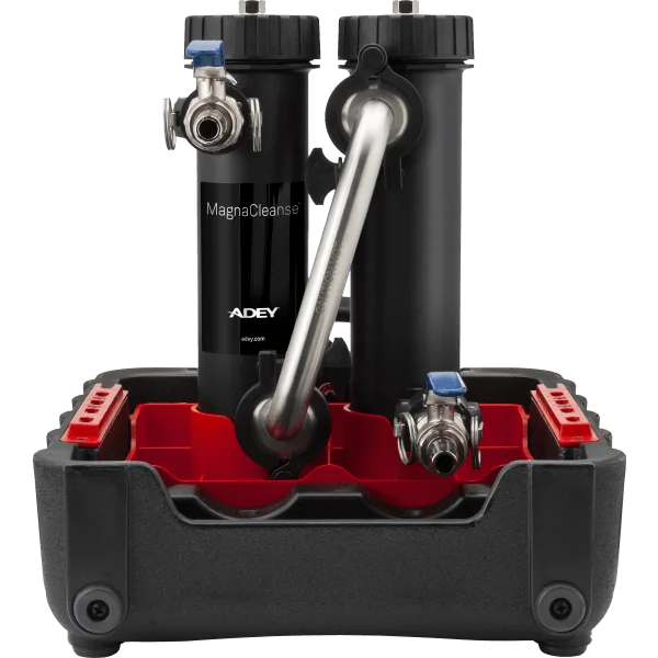
With each new boiler installation package, benefit from a complimentary limescale reducer and system flush, saving you up to £365 compared to competitors.
Click Here
Click Here
Click Here