Buy a Worcester with Installation from £2445. Up to 12 year parts and labour warranty included
Schedule a Worcester Boiler Repair from £108 with 'No Hourly Charges.' Book Today!
Service your Worcester boiler for £108. Ensure safety and efficiency. Book Today!
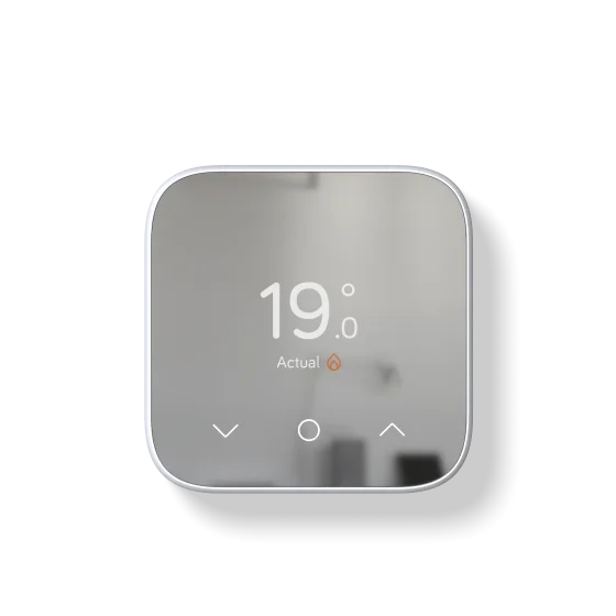
Enhance your Baxi boiler with a smart thermostat from £220. Optimize control and savings!